|
|
||
04/19/04 |
|
|
There are two very separate parts in this crane. The first element is the actual structure and base which serves as a sturdy platform for the second part. The frame is built to specifically resist the forces exerted on it during the lifting phase. Most members are either built to resist tension or compression while others are cross braces inserted to resist torsion as a whole. The Frame (first part):
The Lever Arm (second part):
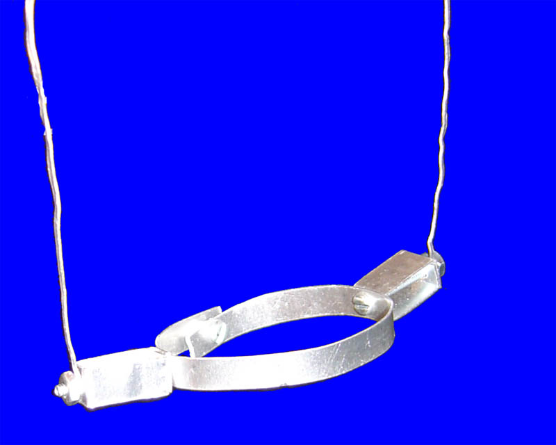
The second part of the crane is the lever arm. This is the moving portion of the crane. It is attached only to the gear about which it revolves. At one end of the arm is the small cradle which is strung down to pick up the actual weight; at the other end is the counterweight. This extra weight is used to assist the servo in lifting the 1-pound weight up the pole. The counterweight originally provides the system with potential energy, which is used in tandem with the power of the servo. When the weight is at its highest, and the counterweight at its lowest, the system is thereby reversed and it is the lifted weight which provides the system with the potential energy to return the counterweight to its original high position. It was found that running the servo at a high rate of speed helped the counterweight return to its starting position more easily because the high speed provided the inertia necessary to return it to its original position (the cradle not touching the weight). The Counterweight: The Cradle Arm:
The Cradle:
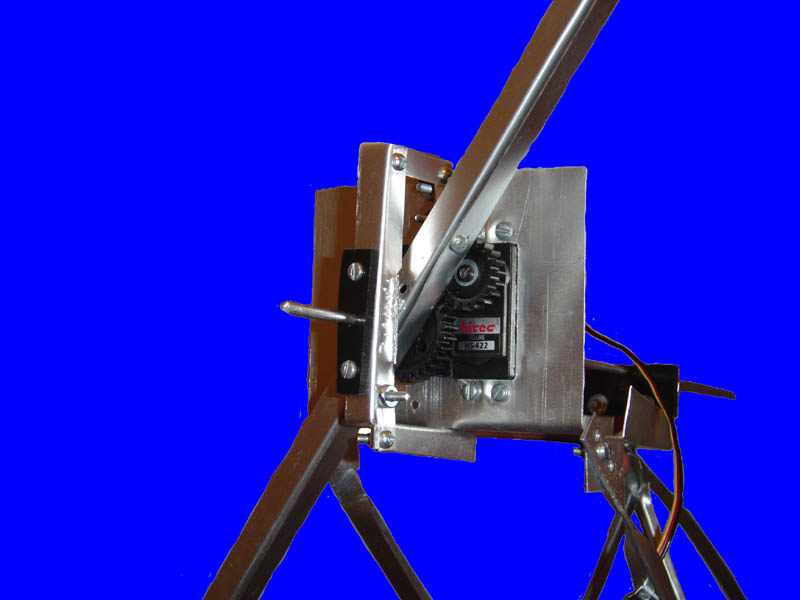
The gearing system is in fact a very simple mechanism: as the servo turns in one direction, the lifting arm rotates in the other direction. The servo and arm are geared 20:40, or 1:2, which means that the arm rotates 50% less than the servo's gear; this means that since the servo rotates about 110°, then the lever arm rotates a total of 55°. For the servo not to move at all during the lifting process, a perfect fitting hole had to be drilled in a solid plate. This insures that there is no movement whatsoever. As can be observed on The Frame and The Gears images, the platform which houses the servo, gears and shaft was constructed from a single flat piece of aluminum which was then shaped into what it is. The Gears:
Next: Performance
This site was last updated 04/19/04 |